Author: Michael Schnick, Institute of Surface and Manufacturing Technology, Technische Universität Dresden, Germany
1 Introduction
Gas Metal Arc Welding (GMAW) is the most important thermal joining technology for metals. GMAW is of vital importance especially for small and medium sized companies (SME) due to its low costs and versatility. During welding arc, weld pool and heated work piece are protected against interactions with the atmosphere by a shielding gas cover. The gas is provided by an external gas which is brought to the process via a welding torch. At the welding torch, and particularly in the gas nozzle, the flow of gas is designed to provide a uniform and possibly laminar free jet flow around the arc and the process. The design of welding torches is mainly based on experience and it has been developed experimentally so far. Since the 1960s, Schlieren shadow graphs has been used to analyze the turbulences of the shielding gas free jet at welding torches without an arc. However, the gas flow during welding and its interactions with the arc are very hard to measure with conventional flow analysis, since the high temperature of up to 20000 K, strong radiation and electromagnetic fields restrict the usage of most standard flow measurement systems in arc welding.
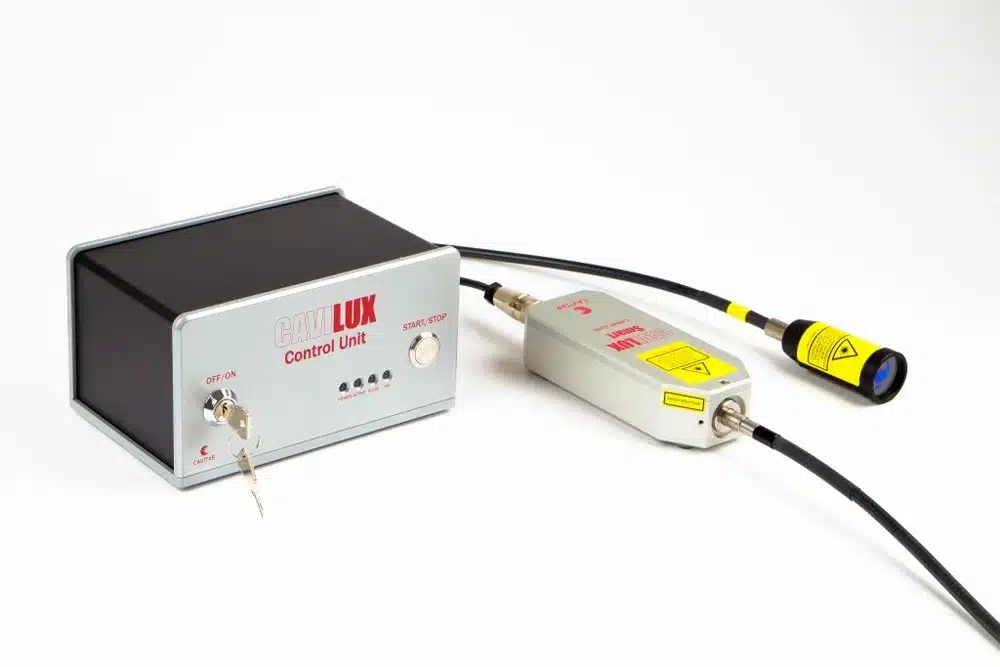
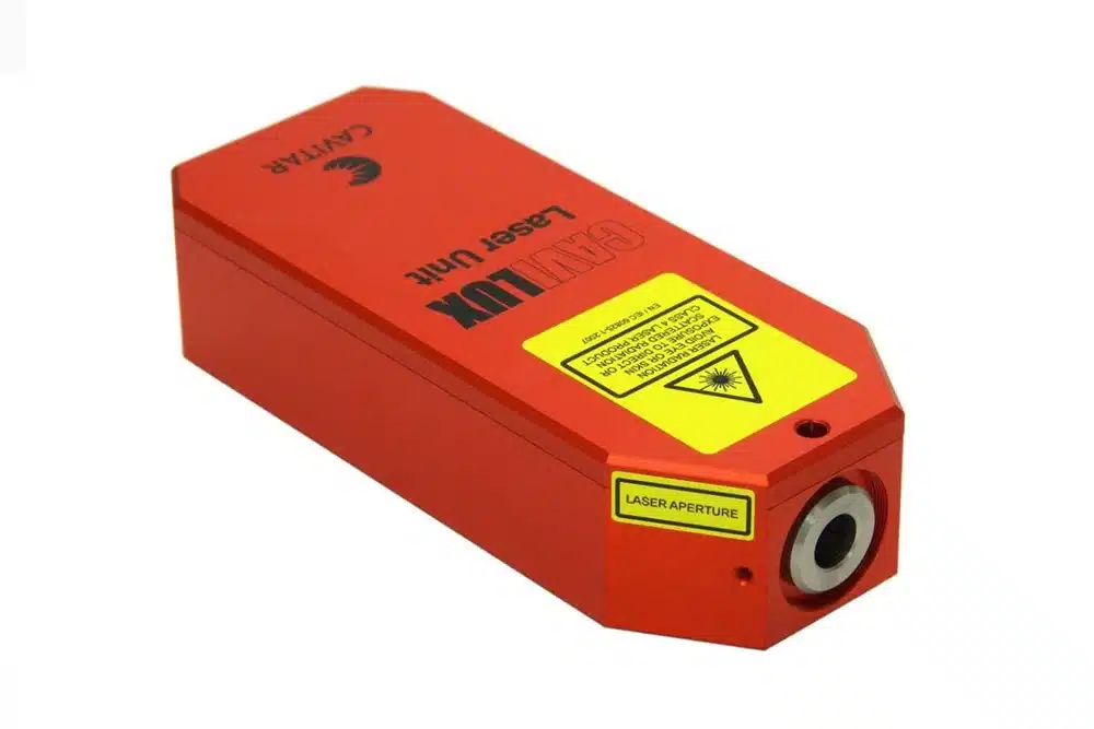
This paper presents a PIV setup, which was especially adapted for measurements of the shielding gas flow in GMAW. The Particle Image Velocimetry (PIV) is a non-intrusive optical method, which enables flow investigations in arc welding processes with relatively high spatial and temporal resolution. The flow describing information in the pictures is derived from tracer particles, which are illuminated by a laser light twice within a defined, short time interval while following the flow. The measurement setup is based on a high-speed camera and a synchronised CAVILUX HF diode pulse laser system. CAVILUX HF enables laser pulses with high frequencies and high pulse power. Thus, for the first time, this laser unit enables time-dependent analyses of the gas flow in arc welding. The laser unit and its optics are both very compact and therefore easy to transport and to use in industrial applications.
2 The measurement method and setup
The PIV measurement system was adapted in order to enable measurements at GMAW welding processes. We used a Photron SA4 High-speed camera with frame rate of 5000 or 10000 fps and pictures of 768 x 1024 or 768 x 512 pixels respectively. The laser unit is coupled with a special optics (prototype) by Cavitar Ltd. that spreads the laser beam to a laser light-section with a thickness of approximately 0.5 mm over a measuring field with a width of 40 mm. In combination with a narrow band-pass interference filter of 808 ± 3 nm the tracer particles are only illuminated by the laser and not by the arc. The optics of the camera and the laser are protected against (metal) spatters by protective classes. In the setup, the work piece is moved under a fixed welding torch. After each measurement, the torch has been disassembled and cleaned with compressed air. Therefore the torch was moved by a robot between a fixed operating and a service positions. The setup is shown in Fig 1.
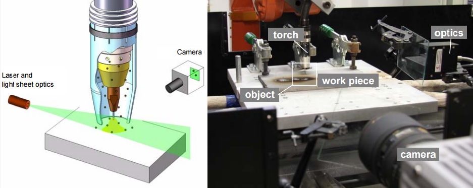
Fig 1: Scheme and photograph of the experimental setup.
Using the PIV system for flow measurements at arc welding processes, two main adjustments are necessary. These adjustments are related to the tracer particles used and to the strong characteristic radiation of the arc. The tracer particles traditionally used in PIV are made of oil or a test fluid such as DEHS generated by compressed air. The diameter of these particles is 0.5 – 50 micrometers. However, the use of water or oil in arc welding is impossible due to procedural and metallurgical restrictions. Thus magnesium oxide particles with a maximum diameter of 1 µm were used for PIV at GMAW. The particles have a melting temperature of 2640°C, a density of 3.65 g/cm3 and extended chemical stability at high temperatures. However, microscopic analyses show that the particles are very bumpy and porous. Therefore the real density of the particles in air should be even smaller and the ability of particles to follow the flow run is very good. Furthermore, tests with a powder doped flow and a welding arc demonstrate that only a small fraction of particles is melted in the arc and deposited as slag onto the welding bath. The majority of the particles pass the flow field without being melted or evaporated by the arc.

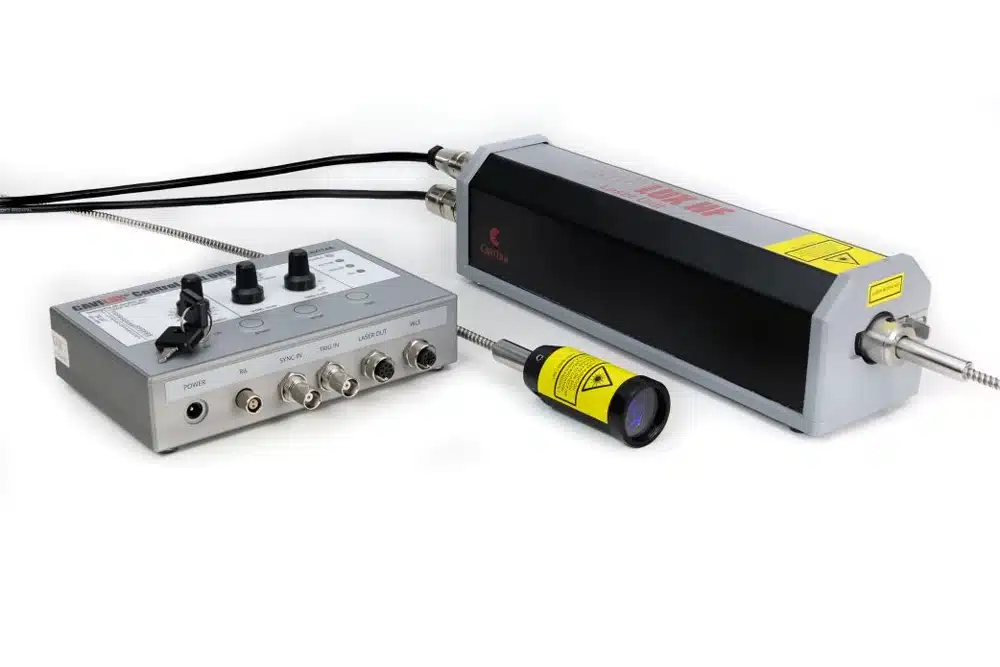
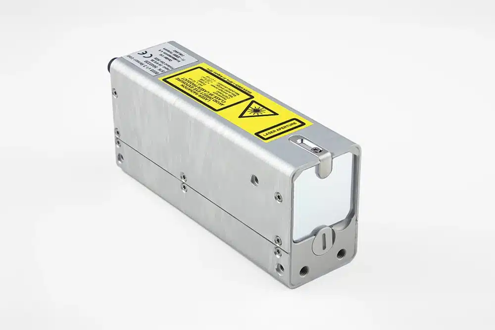
Fig 2: Laser, control unit and prototype of light sheet optics.
The second problem after suitable tracer particles is the radiation of the arc. In GMAW, the arc emits about 1 – 2 kW radiation which is illuminating all particles and overexposing the camera. However, most of the radiation emitted is from metal vapor and of wavelengths below 650 nm. Argon emission from the shielding gas is less intense but there are some intensive lines of atomic argon at 800 and 810 nm. In order to blank the arc radiation a narrow band interference filter of 808 nm central wavelength was used. The filter has a full width of half maximum (FWHM) of ± 3 nm. The interference filter guarantees that the pictures are not overexposed by the arc and the particles are almost only illuminated by the laser. Therefore, with respect to camera torch work piece optics object Laser and light sheet optics Camera Application notes – Industrial monitoring – Welding industry Welding monitoring Flow – PIV Cavitar Ltd › www.cavitar.com the maximum pulse length of the laser, the exposure times of the camera were chosen with ~2.4 µs for 10 000 Hz and a laser pulse length of 2 µs and 1 mJ pulse energy, and a exposure time of ~5.6 µs for 5 000 Hz and a laser pulse length of 4 µs and 2 mJ laser energy. However, first measurements using a conventional light sheet optics demonstrated that the laser intensity in the light sheet was too small. Thus an improved light sheet optics was developed by Cavitar that enables significantly improved exposure of the particles in the sheet (Fig. 2).
The welding process analyzed was a pulsed GMAW process with a peak current of 420 A, a base current of 40 A, and a pulse frequency of 100 Hz. We used a mild steel filler wire (G3Si1) and an Argon-CO2-gas mixture (M21-ArC-18) with various gas flow rates. Two torches were investigated. Torch A was a manual torch with a ø 13 mm gas nozzle and torch B was also a manual torch but with a ø 16 mm gas nozzle. The torches differ fundamentally in their design, Fig 3.
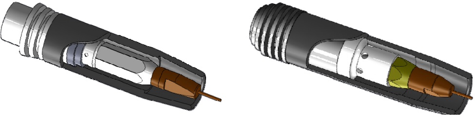
Fig 3: CAD sketches of the investigated torches A (left) and B (right).
The PIV analyses were done using the FlowManager 4.7 (Dantec Dynamics Ltd.) as well as a combined MatLab-LabView-tool programmed by TU Dresden. In both softwares the correlation analysis of the recorded images can be done directly. We used a multi-pass correlation with a final interrogation area size of 16 x 16 pix and 3 refinement steps. A velocity range validation algorithm is used after PIV analyses which excludes all vectors below 0.2 and above 5 m/s.
3 Results
Fig 4 shows an example of particle images and a calculated PIV vector map of the shielding gas flow at the torch B without an arc and with a gas flow rate of 10 slm. The pictures demonstrate that the flow analysis are reliable only in the free jet where particles are present. The flow analysis shows an unsteady back flow region between the wire tip and the work piece.

Fig 4: Examples of particle image (left) and the calculated vector field at torch B without arc (right).
In Figure 5, the mean flow profiles of the free jets of the shielding gas at torches A (left) and B (right) are presented. Both mean flow profiles were calculated from 125 single cross-correlations. The comparison illustrates in particular the impact of the lower diameter of the gas nozzle of torch A and the much smaller flow cross section between gas nozzle and contact tube. As a result, the maximum flow velocities in the free jet of torch A are increased by a factor of 4. In addition, a distinct ”dead water” region is established below the contact tip of torch A. The high gradient of the flow velocity also indicate a high vorticity at the fringes and in the center of the shielding gas free jet. In contrast, the flow profile of torch B is significantly more uniform, and the flow separation region below the contact tube is less established.
The comparison of the flow map at torch A, with and without an arc, demonstrates that the arc influences the flow mainly in the direct vicinity of the process and above the work piece. Thus, the mean flow profiles are very similar with and without arc.

Fig 5: Mean flow profiles of the free jet with a flow rate of 20 slm (ref. vector = 1 x 1 m/s): torch A without an arc (left) and with an arc (middle), and torch B without arc (right).
Fig 6 shows an example of particle images and a calculated PIV vector map of arc welding process with pulsed current. The pictures can be assigned to the base current phase. The droplets are visible due to the thermal induced infrared radiation. The time dependent analyses have demonstrated that the flow in gas free jet is highly affected by the arc. At the beginning of the pulse, the electric currents is increased from 40 to 420 A in 0.6 ms. The PIV analyses demonstrates an immediate expansion of the gas in the arc region and a strong increase of the velocity right beside the process and above the work piece. During the pulse phase the gas inside the free jet as well as the shielding gas towards the arc are accelerated. At the end of the pulse phase increased flow velocities were calculated for the shielding gas flow between the gas nozzle and the arc. At the same time, the diameter of the free jet was reduced slightly. Furthermore, a big swirl was established on the left hand side of the arc. The vortex velocity and the diameter of the swirl change depending on pulse time and the current.

Fig 6: Examples of particle image (left) and the calculated vector field at torch B in a 45 ° pushed position with arc (right).
[embedyt] https://www.youtube.com/watch?v=4pEc6uVdAeA[/embedyt]
Fig 7: Video of calculated vector field at torch B in a 45 ° pushed position with arc.
5 Conclusions
PIV analyses of the shielding gas flow in arc welding processes require serious adjustments to the method of PIV measurement in order to take care of the requirements related to the material and the process as well as in respect to the high temperatures and intense radiation emission of the arc. Thus, it is necessary to use tracer particles with high-melting temperature. Furthermore, a powerful laser with light-sheet illumination optics is needed for an intensive illumination of the particles.
The use of pulsed diode lasers for PIV measurements offers new possibilities for time-dependent flow analyses at gas flow in arc welding. It enables flow analyses up to a frame rate of 10000 fps on gas metal arc welding (GMAW) as well as on gas tungsten arc welding (GTAW). Due to the high laser power the arc can be faded out during base current phase and almost faded out during pulse current phase. However, flow analyses were enabled at short arc (dip transfer mode), pulsed arc and spray arc (spray transfer mode). The results demonstrate that the arc influences the free flow run of shielding gas jet seriously. Thus the flow field at a torch without an arc is very different to flow field within an arc. Especially for short arc and pulsed arc welding, the flow is affected immediately by changes of the electric current. Thus the use of a diode pulse laser for PIV measurements offers new scientific research approaches for optimization of the gas shield quality in GMAW. The measurement system is transportable and can be adapted to industrial welding applications.
About the author
Michael Schnick (Dr.-Ing.) is working as head of group for arc welding processes at Technische Universität Dresden. His research topics are related to numerical and experimental investigation of arcs for welding, spraying and cutting. Contact: Institute of Surface and Manufacturing Technology Technische Universität Dresden 01062 Dresden Germany www.tu-dresden.de