Author: Stuart Laurence, German Aerospace Center (DLR)
1 Introduction
Scramjets (supersonic combustion ramjets) are a technology for high-speed propulsion, potentially allowing large performance advantages over rockets. Despite decades of development, however, significant obstacles remain to the routine deployment of scramjets for access-to-space or high-speed travel. One critical issue associated with scramjets is that of inlet unstart, defined as the upstream displacement or disgorging of the original inlet shock system. The resulting detached shock that forms in front of the inlet leads to large flow spillage, reducing performance, and can also produce violent, unsteady loading on the engine, potentially resulting in its destruction. One possible cause of inlet unstart is abnormal operating conditions inside the combustion chamber of the engine, leading to the upstream propagation of pressure disturbances which can displace the inlet shock system. Such a process was cited as the reason for the failure of the second X-51 flight, for example. In order to predict, detect, and prevent such unstart events, it is thus necessary to study the responsible mechanisms inside the combustion chamber, and to determine how the transient phenomena that accompany incipient unstart may manifest themselves. This is the focus of the present investigation.
2 Experimental configuration
All experiments were performed in the HEG (High Enthalpy shock tunnel Göttingen) facility of the German Aerospace Center (DLR). The HEG is a reflected-shock wind tunnel, capable of reproducing a wide variety of flow conditions at Mach numbers from approximately 6 to 10. The test time of the facility is limited to a few milliseconds; while this still allows the study of a range of high-speed flow problems, it makes visualization, particularly of unsteady phenomena, especially challenging.
The model configuration for the present study is a full-scale reproduction of the fuelled flow path of the HyShot II flight experiment. HyShot II was the first successful test in the HyShot program, run by the University of Queensland, Australia, designed to provide reference supersonic combustion data at hypersonic Mach numbers. The configuration is thus an academic one, rather than a practical thrustproducing engine; however, the simple design and convenient optical access made the Hyshot II an ideal candidate for the present study. The flowpath is shown in the right part of figure 1. The intake consists of a simple 18º wedge; the boundary layer generated on this surface is swallowed by a boundary-layer bleed channel, rather than being allowed to enter the combustion chamber. The combustion chamber is a constant-area duct of 300 mm length, 9.8 mm height and 75 mm width. Hydrogen fuel is injected 58mm downstream of the intake-side leading edge in the wall-normal direction through four port-holes. The exhaust consists of a simple two-dimensional expansion. A schematic drawing of the model inside the HEG test section is shown in the left part of figure 1.
In the present experiments, the wind tunnel was run in a manner to reproduce the flight conditions of the HyShot II flight experiment at 28 km altitude. The free-stream Mach number was approximately 7.4. Hydrogen fuel was injected at various pressures to induce both steady and unsteady combustion conditions.

Figure 1: (Left) Schematic drawing of the HyShot II scramjet model in the HEG test section: (a) HEG nozzle; (b) valve for hydrogen injection. (Right) Flow path for the HyShot II scramjet (upside-down relative to the left schematic): (c) intake ramp; (d) boundary-layer bleed channel; (e) injection location; (f) cowl-side combustion chamber wall; (g) injector-side wall; (h) exhaust surfaces.
An important component of the present study was visualization of the flow and combustion features; thus, windows were installed in the model, providing optical access to almost the entire combustion chamber. The first type of imaging implemented was Schlieren, for which a conventional Z-type arrangement was employed. The Schlieren technique visualizes the first spatial derivative of the flow density, and is thus useful for imaging features such as shocks, boundary layers, and shear layers in compressible flows. Highspeed Schlieren imaging is challenging in facilities such as HEG, because of both the short test times and the significant amounts of self-luminosity produced by the hot gases in the test flow. This luminosity can potentially overwhelm the light source. If the flow is combusting, as in the present case, the luminosity problem is further aggravated. The use of CAVILUX Smart illumination laser for visualization in the present experiments overcame this problem, as the monochromatic nature of the light produced allowed the insertion of a narrow band-pass filter in the light path, effectively removing the self-luminosity. The incoherent nature of the light also eliminated the speckle and diffraction edges typically associated with laser light sources. A further advantage of this light source was the short pulse duration (here ~30 ns), which effectively freezes the flow structures. The CAVILUX Smart was employed together with a Shimadzu HPV-1 high speed camera, with frame rates of 16 or 32 kfps.
The second type of imaging was OH* chemiluminescence visualization, again using the Shimadzu HPV-1 (without a light source). OH is one of the intermediate products in the combustion of hydrogen; thus, the concentration of the electronically excited radical, OH*, gives a good indication of the onset of the flame. OH* also has the advantage of emitting strongly over a narrow wavelength band (near 310 nm), so by placing a narrow band-pass filter of this wavelength in front of the camera, line-of-sight intensity distributions of this radical can be easily obtained. By combining Schlieren and OH* chemiluminescence visualizations then, we can draw links between the flow and combustion features seen inside the combustion chamber.
3 Results
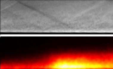
First we concentrate on results obtained for low hydrogen injection pressures, which resulted in steady combustion conditions developing inside the combustion chamber. In figure 2 are shown Schlieren and OH* visualizations of the flow region close to the injection location (the visualized region is approximately 80 mm long). The injection port-holes are located at the lower left corner of each image. The barrel shock created by the interaction of the injected hydrogen with the incoming test-flow is clearly seen in the Schlieren image, as are several of its reflections down the duct. The injection jets themselves are also visible; the freezing of the turbulent structures by the short laser-pulse duration is shown to good effect Application notes – R&D Combustion Schlieren imaging Cavitar Ltd › www.cavitar.com here. The penetration depth is approximately one-half of the duct height by the downstream end of the visualization window. In the OH* image, there is no evidence of combustion occurring directly at the point of injection; rather, combustion appears to be initiated close to the injector-side wall by the first reflection of the barrel shock. The temperature and pressure rise across the shock thus seem to be sufficient to bring the hot hydrogen in the boundary layer to the sides of the injection jets to ignition conditions. Combustion remains isolated to the boundary layer until the second reflection of the barrel shock, which “kicks” the flame further out into the duct and increases the intensity of combustion. These images thus show a clear linkage between the flow and combustion features.
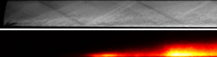
Figure 2: (Above) Schlieren image of the flow in the HyShot II combustion chamber near the injection location (seen at the bottom left corner) for steady combustion conditions. (Below) OH* chemiluminescence image of the same region.
As the amount of injected hydrogen was increased, it was noted from pressure transducer measurements that a pressure disturbance would develop and begin to propagate upstream, signaling the onset of unstart. As the nature of this disturbance was not clear, high-speed visualizations were captured of the unsteady development, and sequences from these are shown in figure 3. In the left column is shown a sequence of the flow region close to the injection location (the same region as in figure 2). Initially (1.4 ms) we see that the picture is similar to that for the steady combustion case (note that the exposure time for the OH* image is reduced here, which explains the apparent weakness of the observed combustion). At 3.5 ms, however, we first see the arrival of a shock structure on the cowl-side wall in the Schlieren image, with an accompanying bulging feature in the OH* image. These continue to move upstream, until a quasi-steady configuration arises from around 4.4 ms, with the shock lodged on the cowl-side wall just downstream of the injectors, and the main combustion region located immediately downstream of the impingement point of this shock on the injector-side wall. The appearance of the OH* structure as it moves upstream suggests the development of a separated flow region on the injector-side wall, as the increased residence time in such regions greatly enhances the hydrogen ignition. Unsteady flow structures in the Schlieren images also support this interpretation. In the final image (7.0 ms), the shock structure has continued moving upstream past the injector, but this is after the steady test time and may be a result of the unsteady inflow conditions that subsequently develop.
In the right column of figure 3 are shown corresponding images from the central combustion chamber further downstream. From 2.5 ms, the development of a shock train on the cowl-side wall is visible; this shock train quickly strengthens and moves upstream. Such shock trains in scramjet combustors are typically caused by one of two mechanisms: boundary-layer separation due to the adverse pressure gradient, or thermal choking due to excessive heat release driving the flow to sonic conditions (at which point a steady flow situation is no longer possible). In the OH* images, a gradual intensifying of the combustion is observed, but notably absent is an OH* feature that follows the shock train motion (as observed in the upstream sequence). This suggests that the shock-train development is not linked to boundary-layer separation, and is rather due to thermal choking, which contradicts the findings of previous authors who have investigated this configuration. The boundary-layer separation observed in the upstream sequence must thus develop at some later point in the propagation of the shock train.

Figure 3: Quasi-synchronous Schlieren and OH* chemiluminescence visualizations of the transient flow (near) near the injector and (right) in the central combustion chamber.
4 Conclusions
Through high-speed Schlieren visualizations employing CAVILUX Smart laser and OH* chemiluminescence imaging, we have investigated the unsteady flow and combustion phenomena leading up to unstart in a model scramjet engine. Incipient unstart was seen to take the form of a shock train that developed in the central combustion chamber and subsequently propagated upstream. By comparing Schlieren and OH* images, we were able to rule out boundary-layer separation as the primary mechanism for this unsteady development (although separated regions were observed further upstream); thermal choking due to excessive heat release was thus isolated as the responsible mechanism.
About the author
Stuart Laurence (Ph.D.) completed his graduate studies at the Graduate Aeronautical Laboratories, California Institute of Technology, in the area of hypersonic flows. He currently works at the German Aerospace Center (DLR), Göttingen, on supersonic combustion, boundary-layer transition, and experimental methods for high-speed flows.