Author: Christian Pabst, Darmstadt University of Technology – Institute for Production Engineering and Forming Machines (PtU)
1 Introduction
Impact welding is a process which enables metallurgical bonds even between dissimilar metals. Electromagnetic pulse welding has been developed as one method for impact welding. It draws its energy from charged high-voltage capacitors. The accelerating force on the workpiece is generated by a coil, through which the current is driven by discharging the capacitors.
The main applications of electromagnetic pulse welding are the construction of hybrid space frames, the gas-tight sealing of high-pressure containers or low-ohmic joints between aluminum to copper for the electromobility. The joints produced with impact welding are very tough, because the joint area is not weakened by thermal influences but exhibits fine grains.
The basic mechanisms are understood and illustrated in Figure 1: One workpiece has to impact another at velocities in the range of roughly about 250 m/s and above. The impact has to occur under a certain impact angle. This leads to a collision point (or line) travelling across the surface. Figure 1: Schematic illustration of impact welding. The impact is accompanied by a bright flash which is characteristic for this process. The metallically pure surfaces are then pressed together by the immense pressure of the impact, which finally evokes the metallurgical joint.

Figure 1: Schematic illustration of impact welding.
2 Experimental Configuration
For the basic investigations, a special test rig has been developed at the PtU. It avoids the drawbacks of explosion welding and electromagnetic pulse welding by colliding and welding flat sheets mechanically. The buildup consists of two rotors which are driven by one motor each. Each rotor holds an aluminum tube with a welding specimen mounted at one side. Figure 2 shows the test rig without housing.

Figure 2: Left: Test rig without housing. Right: Rotors with specimens in collision position.
Both rotors have the same sense of rotation, so the specimens’ velocity adds when they meet in the center. When the specimens are welded successfully, they rip off their clamped rest with the help of a predetermined breaking point. The welded specimens and the clamped parts are shown in Figure 3.

Figure 3: Welded specimens (center) with the clamped parts.
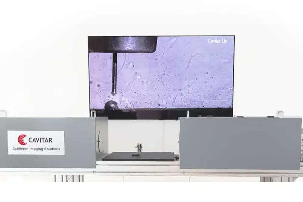
3 Imaging Setup
As the actual impact and the joint formation take place in only few microseconds, the process is hard to capture with a conventional high-speed camera. Hence for these research works, an image intensifier camera is used. It allows exposure times and frame delays in the range of nanoseconds at still remarkable spatial resolutions of up to more than 1000 pixels. Filming the impact is accompanied by two more obstacles in addition to the high speeds: During the impact, a bright flash covers the actual joint area. Its formation will be discussed in the following chapter. Exact triggering is the second challenge, because the camera technique does not allow pre-triggering. Due to the fast turning rotors, the exact measurement of the momentary angle is hardly possible. The bright process glare can be suppressed by a trick which is also used when conventional welding processes are investigated. As the glare is usually white, it can be concluded that its intensity is spread almost constantly across all (visible) wavelengths. The light source that is mandatory for high-quality high-speed images only emits light in a small wavelength range. Thus, its intensity is much greater than the process glare, even if the latter appears to be brighter to the human eye. Figure 4 illustrates this issue.

Figure 4: Emitted wavelength range of the light source and the wavelength distribution of the process light.
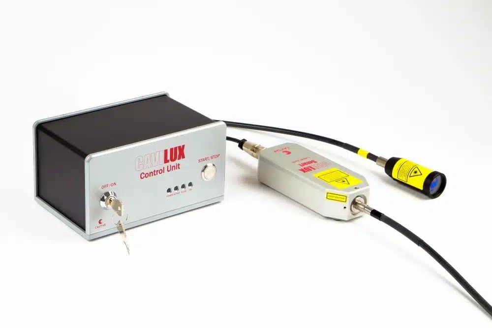
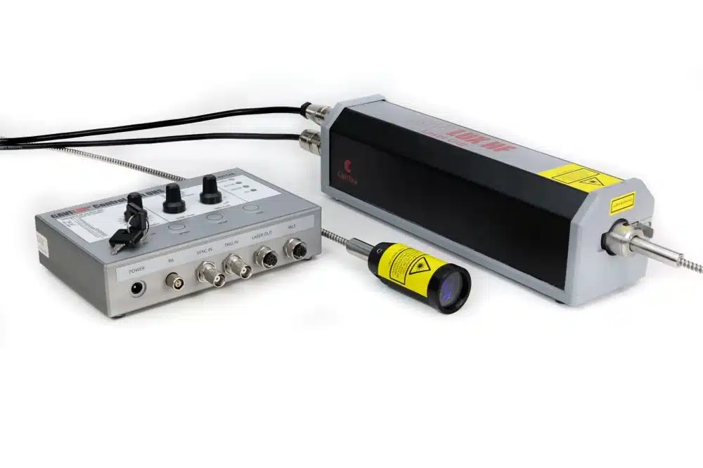
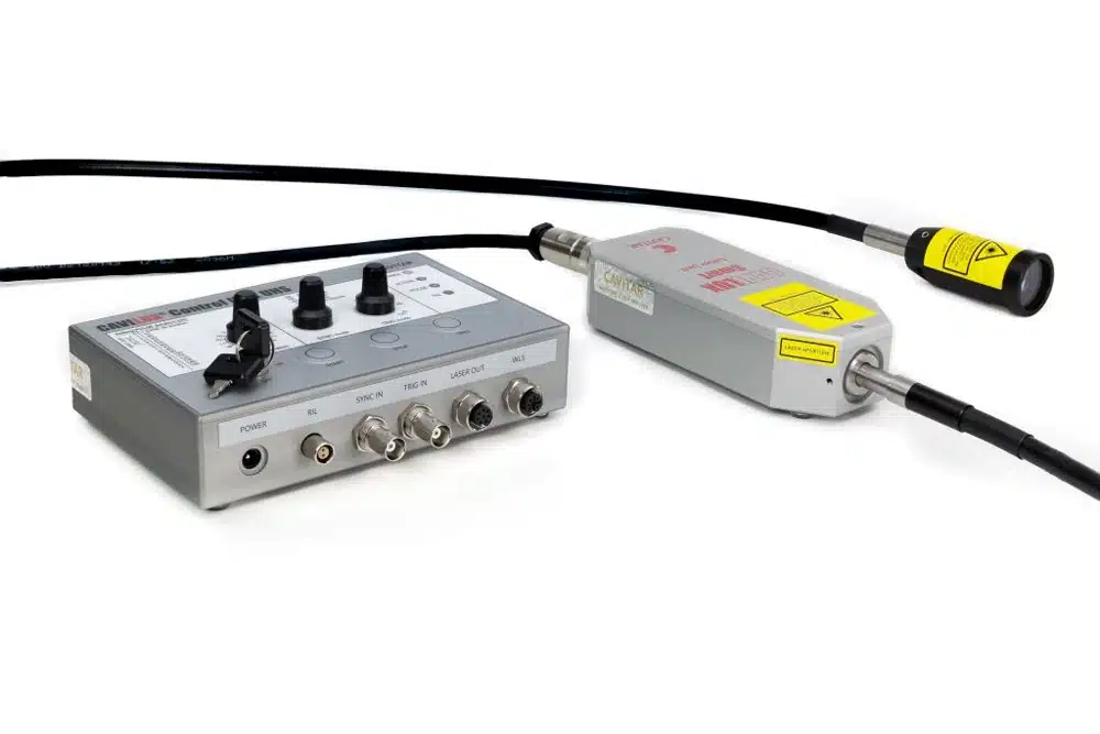
To suppress all other wavelengths, an optical bandpass filter is fitted to the camera in addition to the special light source. In the experiments, CAVILUX Smart laser illumination system with a nominal wavelength of 640 nm ± 10 nm is used together with a filter for 640 nm ± 5 nm. The laser light is comparably easy to handle, because the light is visible and the emitted beam itself is neither coherent nor collimated which prevents speckling. The laser pulses are synchronized with the camera because their length is limited to a few microseconds only due to the limited duty cycle which prevents a constant illumination. Triggering is realized by using the two rotors as a kind of switch for the trigger circuit.
The following Figure 5 shows the process in two independent experiments immediately after the finished impact with and without bandpass filter. It can be clearly seen that it is almost impossible to investigate the impact in detail without the filter.

Figure 5: Propagation of the jet 20 µs after the impact with (left) and without (right) optical bandpass filter.

Figure 6: Image series taken from the side the process with 2 mm aluminum plates at 3 Mio fps.

Figure 7: Image series taken from the side of the process with 0.74 mm steel plates at 2 Mio fps. The process creates also shockwaves which can be seen in the images.
4 Jet Formation and Process Glare
A common explanation for the process glare is that it is caused by the jet. The jet does not only consist of oxides, but also of parent material. The theory states that this parent material burns whilst being emitted and thus causes the intense light. However, it is generally accepted at the same time that high temperatures or even melting do not occur during the impact and welding process. Thus, a sufficient energy source which is capable of initiating the oxidation should actually not exist. In order to examine jetting and glare in more detail, the electromagnetic pulse welding process is investigated under different atmospheres. The complete housing of the test rig has a volume of approximately 1 m³ and is not gas-tight. For the experiments, the coil is covered by an acrylic glass box, which is filled with an inert welding gas. When the enclosure is completely filled with the inert gas, the pulse generator is charged and the weld is established after only few seconds. The following images show the welding of two aluminum sheets with a thickness of 2 mm by a peak current of 300 kA at 20 kHz. Figure 8 shows the welding process with the inert gas atmosphere (left) and with the surrounding air (right). The inert gas does not only significantly decrease the emitted light, but also strongly weakens the emitted pressure wave during the impact.

Figure 8: Electromagnetic pulse welding of two aluminum sheets with (left) and without (right) inert gas atmosphere.
Welds between two copper sheets (Cu-ETP, thickness 1 mm) show a different behavior: Neither the light emission nor the pressure wave is significantly influenced by the surrounding atmosphere. In both cases, it is comparable to aluminum welds with inert gas. These experimental results suggest that an oxidation proceeds during the impact. Aluminum burns with a bright white flame and the oxidation is a highly exothermal reaction. As it can be seen in Figure 5, the emitted jet looks like a cloud of dust. If this dust does not only consist of superficial oxides but also of pure aluminum from the base material, a huge surface is created. Thus, if an appropriate energy source is available, a strong exothermal reaction can occur. This theory is supported by the experiments with the test rig: The extent of the glare and the extent of the jet are almost identical as highlighted in Figure 8. This indicates that jetting and glare are the same phenomenon or at least correlate closely.

Figure 9: Electromagnetic pulse welding of two aluminum sheets with (left) and without (right) inert gas atmosphere.
The auto ignition temperature of aluminum strongly depends on the particle size. The past research work in this field shows that the auto ignition of aluminum powder with a particle size of under 10 µm can already happen at about 600 °C. As burning aluminum is even capable of splitting water molecules, a hydrogen explosion due to the atmospheric humidity might occur as well. Copper on the other hand does not burn, which explains why the surrounding atmosphere does not change the light emission.
5 Conclusions
Through ultra-high-speed imaging employing a CAVILUX Smart laser illumination and image intensifier camera, it was possible to investigate the jet formation and the process glare in electromagnetic pulse welding. The laser illumination enabled the efficient removal of the thermal light emitted by the process. This provided a detailed view behind the bright process light. With back illumination and short pulse duration it is also possible to observe shockwaves.
The high image quality enabled the verification of the theoretical models and to validate research in that area. More information about the theoretical models and considerations for the source of the temperature that is created for the ignition that creates the process glare can be found from: https://eldorado.tu-ortmund.de/bitstream/2003/33500/1/C.Pabst_Electromagnetic%20pulse%20welding.pdf
About the author
Mr. Christian Pabst (M.Sc.) Darmstadt University of Technology
Institute for Production Engineering and Forming Machines
Otto-Berndt-Straße 2
64287 Darmstadt
Germany